-
Home / Products / Mechanical Press / Open Back Double Point Press JH25 Series
OUR PRODUCT
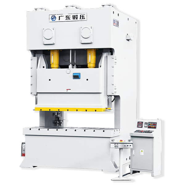
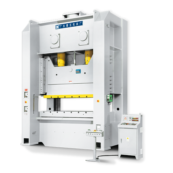
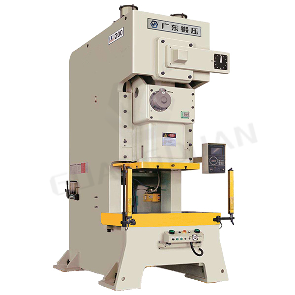
Open Back Double Point Press JH25 Series
It is designed through adopting the high-rigidity frame structure. In addition, it is manufactured though welding the superior – quality steel plates and intimal stress is removed by means of annealing, so stability and reliability of precision of the complete machine are improved.
JH25 SERIES OPEN-BACK DOUBLE-POINY PRESS
It is designed through adopting the high-rigidity frame structure. In addition, it is manufactured though welding the superior – quality steel plates and intimal stress is removed by means of annealing, so stability and reliability of precision of the complete machine are improved.
The double crank shafts are designed in the reverse way, which counteracts side force of the linkage side block and improves stationary of transmission.
It adopts the symmetrical design method of the balancer device, which guarantees relative stationary of the machine’s operation.
Combination of pneumatic wet-type friction plate clutch and brake and double solenoid valve with the famous brand are adopted, so machine have a long service life, lower noise.
The precision of die adjustment can reach 0.1mm and the die adjustment is safe, convenient and reliable; heat treatment quenching and precision grinding are conducted for the gear pair and sliding pair, so the transmission is stable, the precision is high and the durability is strong.
The hydraulic overload protective device is adopted, so the machine can respond rapidly and sensitively and have high security. This machine adopts PLC control method, and it can be provide with the automatic production line uncoiling leveling device to achieve automated stamping of a single machine or many machines.
No information.
| Unit | JH25-110 | JH25-160 | JH25-200 | JH25-250 | JH25-300 | ||
| Nominal capacity | kN | 1100 | 1600 | 2000 | 2500 | 3000 | |
|
Rating Point A.B.D.C. (Above bottom dead center) |
mm | 5 | 6 | 7 | 7 | 7 | |
| Stoke Length | mm | 180 | 200 | 35 | 30 | 30 | |
| Strokes Per Minutes | Fixed | SPM | 50 | 45 | 35 | 30 | 30 |
| Adjustable | SPM | 35-65 | 30-55 | 25-45 | 20-35 | 20-35 | |
| Max. die height | mm | 400 | 450 | 500 | 550 | 550 | |
| Slide adjustment | mm | 90 | 100 | 110 | 120 | 120 | |
| Depth of throat | mm | 350 | 390 | 430 | 470 | 470 | |
| Bolster Area (FB |
mm | 680×1880 | 760×2040 | 840×2420 | 920×2700 | 920×2700 | |
| Thickness of bolster | mm | 150 | 160 | 170 | 180 | 180 | |
| Distance between columns | mm | 1510 | 1650 | 2000 | 2200 | 2200 | |
| Slide Area (FB |
mm | 520×1420 | 580×1500 | 650×1850 | 700×2100 | 700×2100 | |
| Shank hole(Diameter/depth) | mm | Φ60×75 | Φ60×80 | Φ70×90 | Φ70×100 | Φ70×110 | |
| Main motor | kW | 11 | 15 | 22 | 30 | 30 | |
| Motor for slide adjustment | kW | 1.1 | 1.5 | 3 | 3 | 3 | |
| Bolster to ground | mm | 900 | 900 | 1000 | 1100 | 1100 | |
| Overall dimension | LR | mm | 2300 | 2360 | 2830 | 3160 | 3180 |
| FB | mm | 1880 | 2070 | 2460 | 2750 | 2820 | |
| H | mm | 3170 | 3435 | 4250 | 4655 | 4655 | |
| Total Weight (net) | kg | 15000 | 21000 | 32000 | 40000 | 42000 | |
| Cushion (Optioanl ) | Capacity | kN | 2×50 | 2×80 | 2×100 | 2×140 | 2×140 |
| Stroke length | mm | 70 | 100 | 100 | 110 | 110 | |
| Air pressure used | MPa | 0.6 | 0.6 | 0.6 | 0.6 | 0.6 | |
Remarks: Specification are subject to change without notice.
| Dimensions of the Bolster and Slide | Model | JH25-100 | JH25-160 | JH25-200 | JH25-250 | JH25-300 | |
| (mm)
|
Bolster Area | w | 400 | 400 | 400 | 400 | 400 |
| b | 680 | 760 | 840 | 920 | 920 | ||
| j | Φ30 | Φ30 | Φ30 | Φ30 | Φ30 | ||
| f | 250 | 275 | 320 | 375 | 375 | ||
| g | 250 | 250 | 300 | 300 | 300 | ||
| y | 400 | 400 | 500 | 470 | 470 | ||
| h | 700 | 700 | 800 | 800 | 800 | ||
| v | 800 | 800 | 1000 | 910 | 910 | ||
|
|
i | — | — | 1200 | 1200 | 1200 | |
| d | 1200 | 1200 | 1500 | 1350 | 1350 | ||
| z | — | — | — | 1790 | 1790 | ||
| z1 | 1600 | 1600 | 2000 | 2230 | 2230 | ||
| a | 1880 | 2040 | 2420 | 2700 | 2700 | ||
| k | 1100 | 1060 | 1100 | 1200 | 1200 | ||
|
|
x | 150 | 200 | 200 | 200 | 200 | |
| Cushion pins | qxr | 4×100 | 5×100
|
6×110
|
6×110
|
6×110
|
|
| sxt | 3×100
|
4×100
|
4×100
|
4×100
|
4×100
|
||
| u | 40 | 60 | 70 | 70 | 70 | ||
| e | 300 | 300 | 320 | 360 | 360 | ||
|
|
T slot | a1 | 22 | 22 | 22 | 28 | 28 |
| b1 | 37 | 37 | 37 | 48 | 48 | ||
| c1 | 24 | 24 | 24 | 28 | 28 | ||
| d1 | 16 | 16 | 16 | 20 | 20 | ||
|
|
Slide area | A | 400 | 400 | 500 | 470 | 470 |
| J | 800 | 800 | 1000 | 910 | 910 | ||
| E | — | — | — | 1350 | 1350 | ||
| B | 1200 | 1200 | 1500 | 1790 | 1790 | ||
| G | 1420 | 1500 | 1850 | 2100 | 2100 | ||
| H | 250 | 250 | 400 | 300 | 300 | ||
| D | 520 | 580 | 650 | 700 | 700 | ||
| Y | 150 | 170 | 180 | 225 | 225 | ||
| C | Φ60 | Φ60 | Φ70 | Φ70 | Φ70 | ||
JH25 SERIES CONFIGURATION
Standard Configuration
T-shape two-hand button operating board (movable)
Hydraulic overload protective device
Accumulative 8-bit counter
Preset 4-bit counter
Motor-driven slide block adjustment device
Automatic lubricating device
Misfeed detecting interface
Electronic cam controller
Programmable controller
Double solenoid valve
Digital die height indicator(Unit:0.1mm)
Wet-type Clutch
Slide block and die balancing device
Electronic type crank angle indicator
Frequency control of motor speed
Inversion set of the main motor
Coupling for air blowing
Coupling for air source
Operating instruction and precision inspection table
Shockproof sizing block
Over-run protective device
Optional Configuration
Air cushion
Foot switch
Photo-electric protection
Quick die change device
Flywheel brake equipment
Die safety detector
Foundation bolt
Safety net
Lighting lamp for die
Mechanical cam controller
CONTACT US

Guangdong Metal Forming Machine Works Co., Ltd.
We are always providing our customers with reliable products and considerate services.
If you would like to keep touch with us directly, please go to contact us
 Bolster area (standard)
 Bolster area (For cushion)
 Square opening on bolster (OPTIONAL)
 T-Slot
 Slide Bolster